Overview
What is BFD?
Bidirectional Forwarding Detection (BFD) as defined in RFCs 5880 and 5881 is a protocol to detect network faults between the forwarding planes of two network devices. It is designed as a low-overhead protocol that can run over media that may not have built-in failure detection, including Ethernet, tunnels, and MPLS LSPs. Multiple control plane protocols can subscribe to a BFD session to be notified when connectivity is interrupted. This can help with faster convergence after a failure, as the IGP(s) do not have to wait for a connectivity timeout in their protocol.
What is different about broadcast networks?
I’ve always used BFD in situations where I had a logical point-to-point link between two devices. While integrating a new network, I discovered a situation where BFD was a useful tool in a multiaccess broadcast network.
Topology
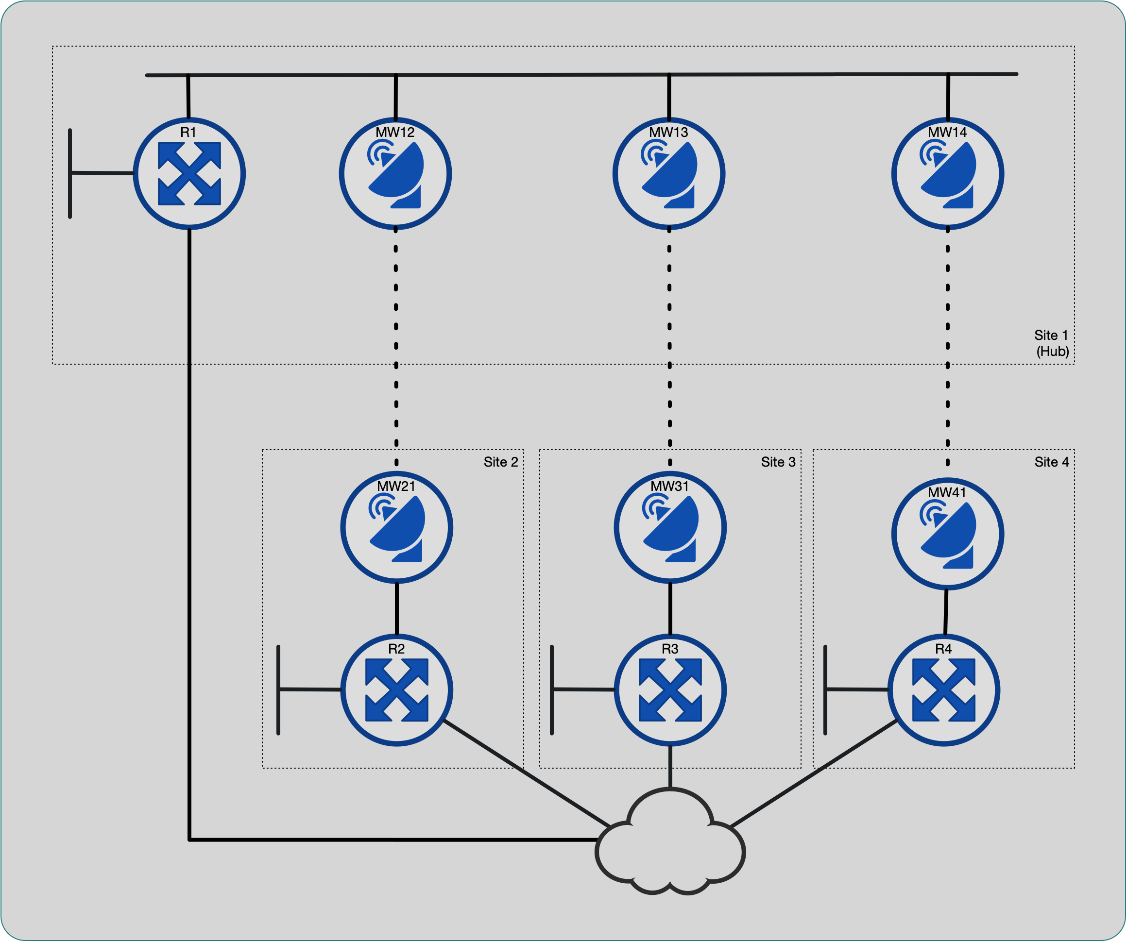
The network is a simple four-site hub-and-spoke topology. Each site has a microwave link back to the main site, configured as a transparent layer 2 bridge. In addition, the single router at each site has a backup link to another routed network.

Four sites in a hub-and-spoke arrangement
The original design treated each hub-to-spoke link as a routed
point-to-point interface. At implementation time, it was noticed that
there weren’t enough interfaces on the hub router, R1, to accommodate
these links. The folks building the hub site added a switch to connect
all the microwave links (and the one router interface), and configured
the wireless links as a single flat network.

Hub site is switched
Given the new physical topology, I considered configuring each hub site wireless bridge in a separate VLAN and trunking them all to the router interface. By configuring 802.1q subinterfaces on the router, we could still have a point-to-point routed topology. After discussion with the Radio installers, we decided to keep the topology flat network. One advantage of this is that the spoke sites can still communicate with each of if there is a router failure at the hub site.
Failover detection
The requirements are for this network to use the backup network as an alternate path in case of failure of the microwave links. With default OSPF timers, failover detection would be too slow for the application. It was an option to tune these timers for faster reaction, but I tend to avoid this choice and use BFD if it is supported on the hardware (and usually is on modern gear). My “go to” solution here is BFD.
My experience with BFD has only been with point-to-point links in situations where one cannot rely on interface link status to change when the remote device interface is down. I was unsure how this would work on a broadcast network with multiple adjacencies, so I decided to do some investigation.
Lab
My first step was to lab this up. I booted up a four router and switch topology in GNS3 and started to configure BFD. As soon as I configured it, GNS3 immediately crashed.

I tried a few things (different timers, different hardware models, etc.) before I searched online and found others reporting the same thing: GNS3 does not support BFD. Oh, well. Fortunately, the system hadn’t been put into production when I started this integration, so I was able to test this configuration live. The output snippets included in this post are from the actual gear, with names and IPs changed.
Configuring BFD
Echo mode
Apparently, BFD started as a polling-only mode. These control packets need to hit the router’s CPU for processing, so response time can be affected by CPU load. With aggressive timers (as low as 50ms) and multiple adjacencies, this could cause false failures, so “echo” mode was introduced.
With BFD echo mode enabled, which is usually the default, the router
will send echo packets at the configured interval rate. It will also
send traditional control packets (to negotiate timers, etc.) using the
slow_timer rate. BFD control messages use a destination of UDP port
3784 and echo messages use UDP port 3785.
The way echo messages work is a very clever hack. The sender sets the source IP address to its own address. This way, the receiving router forwards the packet right back to the sender using only the forwarding path, usually in hardware without involving the CPU.
Frame 2156: 54 bytes on wire (432 bits), 54 bytes captured (432 bits)
Ethernet II, Src: Cisco_93:73:80 (54:9f:c6:93:73:80), Dst: Cisco_8f:8e:00 (54:9f:c6:8f:8e:00)
Internet Protocol Version 4, Src: 10.0.0.2, Dst: 10.0.0.2
User Datagram Protocol, Src Port: 49152, Dst Port: 3785
BFD Echo message
Echo mode did not work in this particular network; the adjacencies would
not establish. From my packet captures on the routers, the BFD echo
packets were sent but never received. I believe they were filtered by
either the wireless bridges or the intermediary switch, but wasn’t able
to troubleshoot further as I didn’t have administrative access to those
devices. Once I disabled echo mode on the interface, using no bfd echo, everything started working.
Timers
BFD uses three setting to control the rate and sensitivity of packets.
The interval is the rate (in milliseconds) of transmitted packets,
min_rx is the minimum rate (again, in milliseconds) packets are
expected from the peer, and multiplier is the number of successive
missed packets before BFD declares the session down.
I started with a 50ms interval with a multiplier of 3, the lowest
value supported on the Cisco hardware I was using. I did some quick
load testing on the wireless links, and was able to cause a BFD failure
event. I was also concerned about any CPU load, so I set the interval
to 100ms and multiplier to 9, bfd interval 100 min_rx 100 multiplier 9, so that I would still have subsecond reaction to peer failure.
This is one of the common intervals recommended in RFC7419.
There is also a bfd slow-timers global setting, that defaults to
1000 milliseconds, that controls the rate of control messages when
echo mode is used.
Results
The BFD configuration on each router consisted of:
interface GigabitEthernet0/0/0
 ip pim bfd
 ip ospf bfd
 bfd interval 100 min_rx 100 multiplier 9
 no bfd echo
Clients
One of the advantages of BFD, is that multiple protocols can “subscribe” to the same BFD session. In this way, there is only a single high-rate, high-sensitivity protocol running between any two peers. Other IGPs on the same device – such as OSPF, OSPFv3, BGP, PIM, even static routes – can be configured as BFD clients to get notified of any failure events.
In this particular case, we are running OSPF and PIM.
R1#show bfd summary client

Client              Session          Up          Down
OSPF                      3           3             0
CEF                       3           3             0
PIM                       3           3             0

Total                     3           3             0
Sessions
When BFD is enabled for OSPF on a broadcast network, it will only create sessions with the DR and BDR. I’ve changed OSPF priorities so that the hub site (R1) is the DR and R2 is the BDR.
R1#show bfd neighbors client ospf

IPv4 Sessions
NeighAddr                              LD/RD         RH/RS     State     Int
10.0.0.2                                3/1          Up        Up        Gi0/0/0
10.0.0.3                                1/1          Up        Up        Gi0/0/0
10.0.0.4                                2/3          Up        Up        Gi0/0/0
R2#show bfd neighbors client ospf

IPv4 Sessions
NeighAddr                              LD/RD         RH/RS     State     Int
10.0.0.1                                1/3          Up        Up        Gi0/0/0
10.0.0.3                                3/3          Up        Up        Gi0/0/0
10.0.0.4                                2/1          Up        Up        Gi0/0/0
R3#show bfd neighbors client ospf

IPv4 Sessions
NeighAddr                              LD/RD         RH/RS     State     Int
10.0.0.1                                1/1          Up        Up        Gi0/0/0
10.0.0.2                                3/3          Up        Up        Gi0/0/0
R4#show bfd neighbors client ospf

IPv4 Sessions
NeighAddr                              LD/RD         RH/RS     State     Int
10.0.0.1                                3/2          Up        Up        Gi0/0/0
10.0.0.2                                1/2          Up        Up        Gi0/0/0
Conclusion
I was able to do some failover tests both with and without BFD enabled. The (voice) application did not show any noticeable impact when using BFD, but audio was dropped without it (relying on the standard OSPF 40-second dead interval). The additional packet overhead of BFD does not significantly impact the wireless network.
This adventure gave me a chance to learn a little bit more about a protocol I use every day. I better understand the failure modes of the protocol and how it interacts with the network and devices.